Continuous-Time Ratiometric
Linear Hall Effect Sensor ICs
A1301 and
A1302
8
Allegro MicroSystems, LLC
115 Northeast Cutoff
Worcester, Massachusetts 01615-0036 U.S.A.
1.508.853.5000; www.allegromicro.com
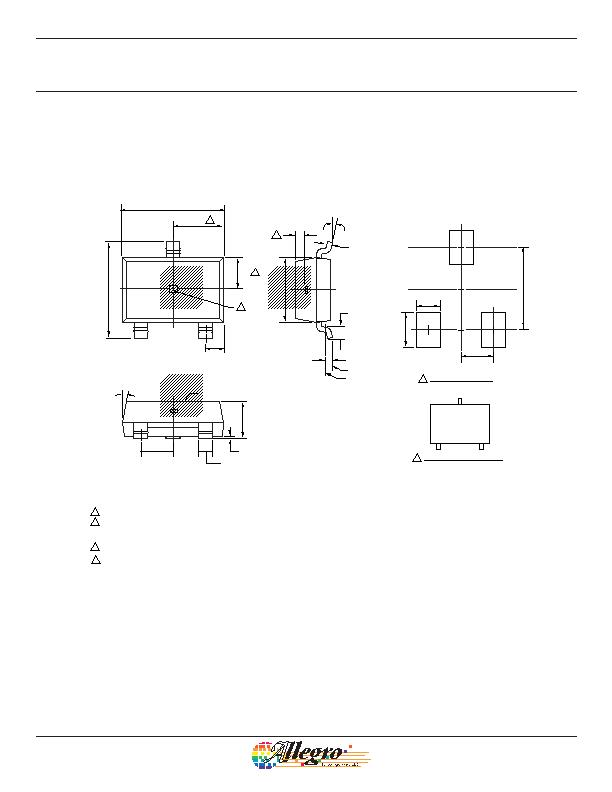
Package LH, 3-Pin; (SOT-23W)
0.55 REF
Gauge Plane
Seating Plane
0.25 BSC
0.95 BSC
0.95
1.00
0.70
2.40
2
1
A Active Area Depth, 0.28 mm REF
B
C
C
B
Reference land pattern layout
All pads a minimum of 0.20 mm from all adjacent pads; adjust as necessary
to meet application process requirements and PCB layout tolerances
Branding scale and appearance at supplier discretion
A
PCB Layout Reference View
Standard Branding Reference View
1
Branded Face
N = Last two digits of device part number
T = Temperature code
NNT
2.90
+0.10
0.20
8X 10?REF
0.180
+0.020
0.053
0.05
+0.10
0.05
0.25 MIN
1.91
+0.19
0.06
2.98
+0.12
0.08
1.00 ?.13
0.40 ?.10
4氨4?/DIV>
For Reference Only; not for tooling use (reference dwg. 802840)
Dimensions in millimeters
Dimensions exclusive of mold flash, gate burrs, and dambar protrusions
Exact case and lead configuration at supplier discretion within limits shown
D Hall element, not to scale
D
D
D
1.49
0.96
3
发布紧急采购,3分钟左右您将得到回复。
相关PDF资料
A1323LLHLT-T
IC SENSOR HALL EFFECT SOT23W
A1351LKTTN-T
IC SENSOR HALL EFFECT 4-SIP
A1354KKT-T
IC SENSOR HALL EFFECT 4-SIP
A1356LKB-T
IC SENSOR HALL EFFECT 3 SIP
A1361LKTTN-T
IC HALL EFFECT SENSOR LN 4-SIP
A1374EKB-T
IC SENSOR HALL EFFECT PREC 3-SIP
A1422LK
IC SENSOR HALL EFFECT AC 4-SIP
A1425LK
IC SENSOR HALL EFFECT AC 4-SIP
相关代理商/技术参数
A130-3
功能描述:SCREWDRIVER SLOTTED 1/8" 4.88" 制造商:klein tools, inc. 系列:- 零件状态:在售 工具类型:螺丝刀 尖头 - 类型:开槽型 尺寸:1/8" 长度 - 插片:3.00"(76.2mm) 长度 - 总:4.88"(124.0mm) 特性:黑色刀头,表面镀铬,口袋夹 重量:0.04 磅(18.14g) 标准包装:12
A1303/4
制造商:DORMER 功能描述:DRILL TAPER SHANK HSS 3/4"
A1303/8
制造商:DORMER 功能描述:DRILL TAPER SHANK HSS 3/8"
A13030
制造商:ABB 功能描述:130-30
A130-30
制造商:ABB 功能描述:130-30
A13030.0
制造商:DORMER 功能描述:DRILL TAPER SHANK HSS 30MM
A13032.0
制造商:DORMER 功能描述:DRILL TAPER SHANK HSS 32MM
A13034.0
制造商:DORMER 功能描述:DRILL TAPER SHANK HSS 34MM
